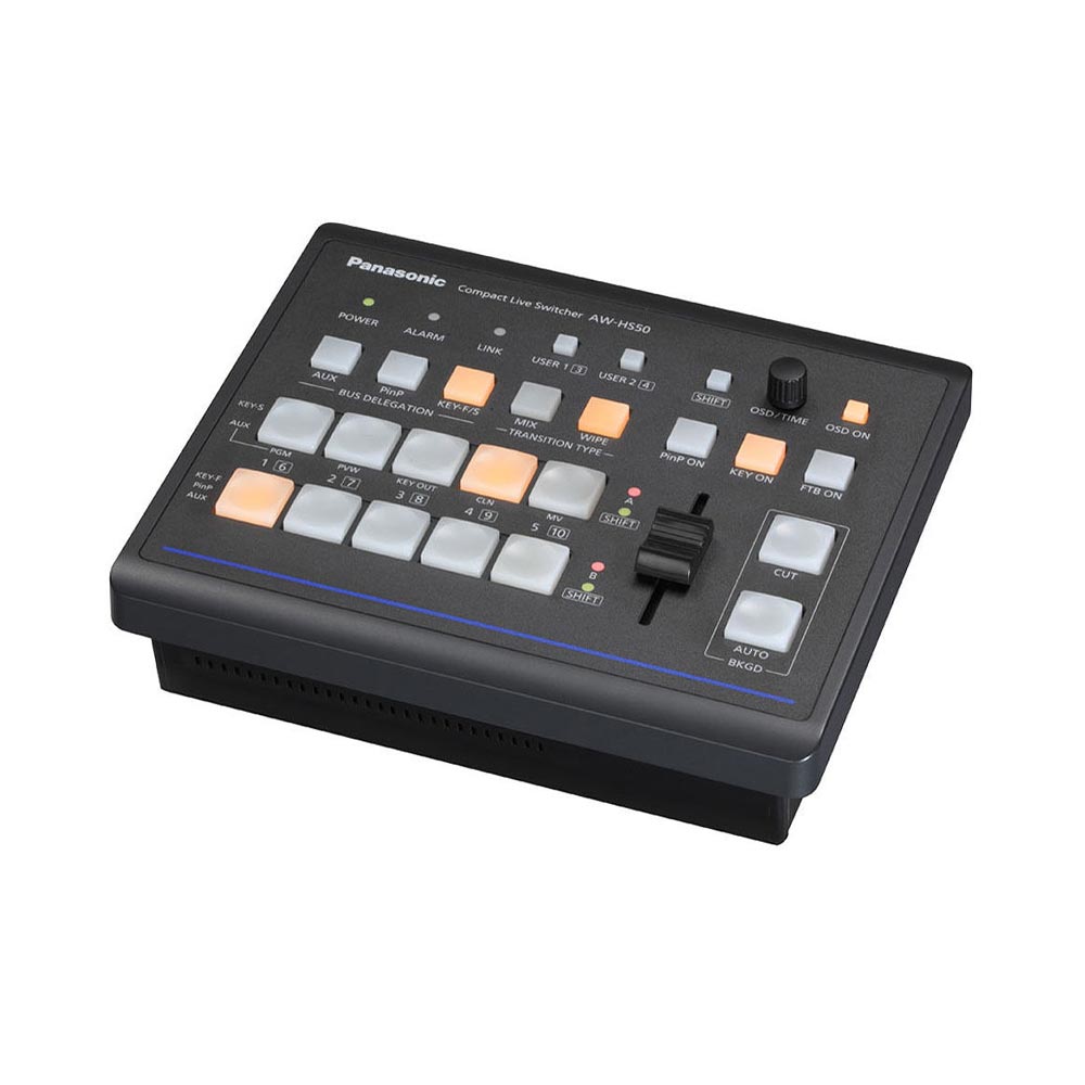
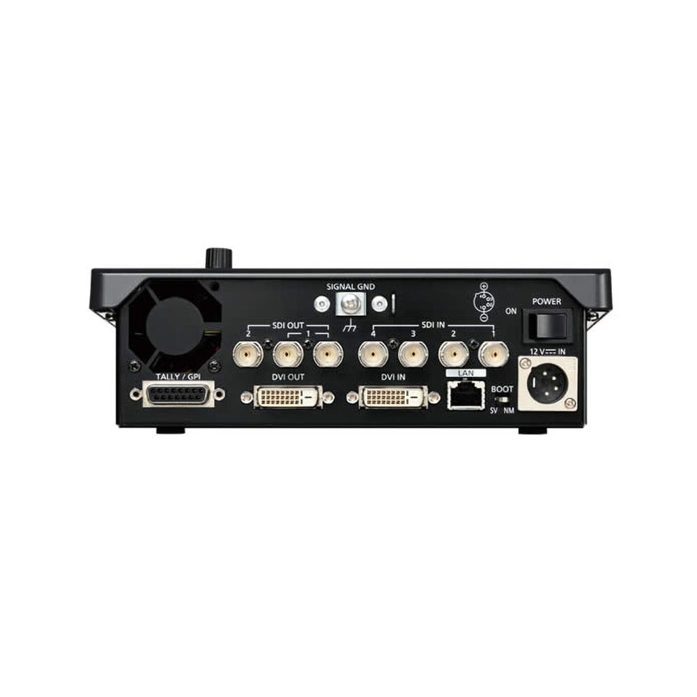
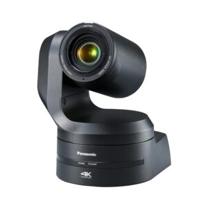
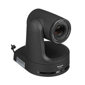
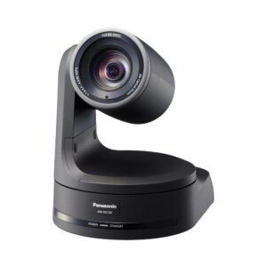
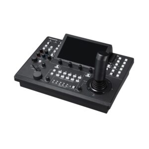
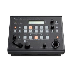
This is a half-rack size digital video switcher. In spite of its compact size, it features four SDI inputs, one DVI-D input, two SDI outputs, and one DVI-D output. A MultiViewer Display function lets you split the screen in eight different ways, and a Frame Synchronizer ensures easy, high-quality switching. By combining the AW-HS50 with the AW-HE50S HD Integrated Camera and AW-RP50 Remote Camera Controller, a space-saving, low-cost HD image production system can be configured for business use.
Panasonic Compact Live Switcher AW-HS50
| Data Sheet |
click here |
| Dimensions (W x H x D) | 210 x 67 x 177 mm (8-1/4˝ x 2-5/8˝ x 6-15/16˝) [excluding protrusions] |
| Current consumption | 2.0 A (DC 12 V) |
| Power Requirements | DC 12 V ±10 % (AC adapter provided) |
| Humidity | 10 % to 90 % (no condensation) |
| Ambient Operating Temperature | 0 °C to 40 °C (32 °F to 104 °F) |
| Mass | 1.4 kg (3.08 lbs.) |
| Signal Processing | Y:Cb:Cr 4:2:2, 10 bit (8 bits for frame memory) RGB 4:4:4, 8 bit |
| ME Number | 1ME |
| SDI Inputs | HD: Serial digital component (SMPTE 292M) SD: Serial digital component (SMPTE 259M) 4 signal lines: SDI IN 1 to SDI IN 4 HD: SMPTE 292M (BTA S-004B) standard complied with SD: SMPTE 259M standard complied with |
| Video Terminal | SD: 480/59.94i, 576/50i HD: 1080/59.94i, 1080/50i, 720/59.94p, 720/50p, 1080/24PsF, 1080/23.98PsF |
| Inputs | 5 video lines SDI 4 signal lines: SDI IN 1 to SDI IN 4 DVI-D 1 signal line: DVI IN |
| Outputs | 3 video lines, 4 outputs SDI 2 signal lines: SDI OUT 1, SDI OUT 2 (Only the SDI OUT 1 signals are split into two) DVI-D 1 signal line: DVI OUT |
| DVI-D Input | Digital RGB (Vertical frequency: 60 Hz): XGA (1024 x 768), WXGA (1280 x 768), SXGA (1280 x 1024), WSXGA+ (1680 x 1050), UXGA (1600 x 1200), WUXGA (1920 x 1200) Digital RGB: 1080/50p, 1080/59.94p • Analog input signals are not supported. |
| SDI Outputs | HD: Serial digital component (SMPTE 292M) SD: Serial digital component (SMPTE 259M) 2 signal lines: SDI OUT 1, SDI OUT 2 HD: SMPTE 292M (BTA S-004B) standard complied with SD: SMPTE 259M standard complied with |
| DVI-D Output | Digital RGB (Vertical frequency: 60 Hz): XGA (1024 x 768), WXGA (1280 x 768), SXGA (1280 x 1024), WSXGA+ (1680 x 1050), UXGA (1600 x 1200), WUXGA (1920 x 1200) Digital RGB: 1080/50p, 1080/59.94p • High-resolution multi view mode supported: Signals are also output with a high resolution even when SD has been selected as the system mode. When the high-resolution multi view mode is enabled, MV is assigned to the DVI OUT connector, and MV cannot be assigned to the SDI OUT 1 connectors or SDI OUT 2 connector. • Analog output signals are not supported. |
| LAN | RJ-45 x 1 10BASE-T/100BASE-TX (For IP control) Connecting cable: LAN cable (category 5 or above), max. 100 m [328 ft.], STP (Shielded Twisted Pair) cable recommended • When connecting to a hub (switching hub), use a straight cable. Use a crossover cable when connecting the unit and another device on a 1:1 basis without going through a hub. |
| Accessories | Operating Instructions (this manual), CD-ROM (Operating Instructions , Operating Instructions , Data Transmission Software), AC adapter, Power cable (2 m [6.6 ft.]) |
| Video Delay Time | 1 frame (F) • Video signals that have passed through the PinP, multi view display, DVI-D input or DVI-D output will be delayed in each case by up to one frame. |
| Other | SERVICE switch [SV/NM] (for maintenance purposes) Normally, this switch is used as the “NM” position. |
| TALLY/GPI | D-sub 15-pin, female, inch thread INPUT: 5 inputs, photocoupler sensing OUTPUT: 7 outputs, open collector output (negative logic) |
| Synchronous Terminal | – |
| Control Terminal | – |


